Posi-Stop Sandline Plus System Products
Posi-Stop Sandline Plus System

The Posi-Stop Sandline Plus System is an electronic
system to monitor and control Sandline depth, speed and weight to avoid the tool
basket from leaving the well or hitting the bottom of the well at unsafe speeds or
unsafe tension (weight) on the Sandline. System works in conjunction with Dynamic
Brake System.
The system will include the following features and controls:
-
- Provide audible alarm when the basket reaches operator defined depth (alarm will increase frequency of beeps to indicate Sandline is approaching the surface or lower limit)
- Provide audible alarm when line speed exceeds set limits (limits can be set for each defined depth(s) to gradually lower the speed limit as the Sandline nears the surface and/or lower set limit)
- Provide Audible Alarm when Weight Limit is reached (Each audible alarm will be unique)
- Provide speed control protection at surface and lower limit (operator defined) starting at a defined depth above/below limits by activating modulating valve to gradually apply brake to slow the line speed.
- Provide upper and lower limit full stop protection (gradual application of brake system starting at defined depth to avoid snapping the line and drop the throttle and clutch). System allows for operator bypass of full stop at limits by engaging a bypass switch (has built-in 10 second timer to avoid continual bypass mode)
- Provide weight on line protection utilizing electronic load pin technology to determine weight on line and when operator defined set limit is reached the brake is applied and air to throttle and clutch is dropped.
- Easy depth reset at surface to correct any errors in depth reading due to sheave not rotating correctly with Sandline (greased line moves without rotating sheave)
Sandline Plus System Kit includes:
-
- Sandline Plus Console
- Encoder (Prox Switches and Target Wheel Mounted on the Sandline Sheave) to determine speed and depth by counting rotations of the sheave
- Encoder Connecting Cable (including connector)
- Electronic Load Pin with wiring harness
- Digital Weight Gauge with connecting cable and protective enclosure
- Modulator Valve Assembly (Not pictured)
- Solenoid Valve Assembly (Not pictured) to release air supply to clutch and throttle
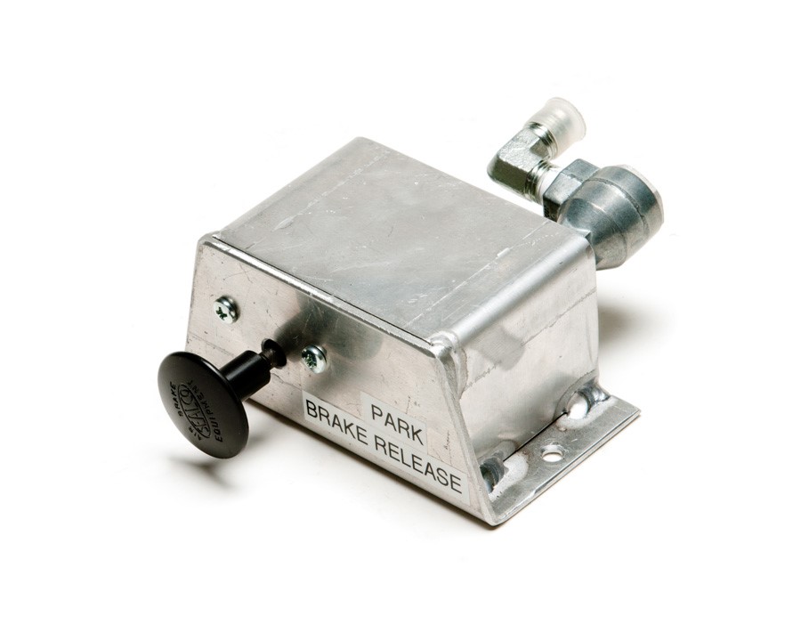
- Park Brake Switch
Installation
Posi-Stop Sandline Plus System
Console
A mount will be required to be placed near the Sandline
Operator station. The operator will need to be able to reach the controls on the console
and be able to see the displays. The console will bolt onto the mount to allow easy
removal for maintenance and repair. Power supply from the rig will be provided
preferably from the rig battery bank to the console. If power is supplied from the
starter then fuse protection will be required.
Encoder
The encoder consists of a two-piece circular target plate
that will bolt onto the sheave. The target plate will have circular cut outs that will
allow the proximity switch sensors to monitor rotation and direction of the sheave to
provide depth and speed data collection. The proximity switches are mounted on a 4
inches plate with the switches spaced to match target spacing. The proximity switches
are connected to a junction box that will require mounting at the crown spaced per
target requirements above the target plate.


The prox switch assembly connects to the console by routing
the encoder cable down the rig mast to the console. The cable should be protected by
conduit. The cable route will be a long cable running down the mast to a connector at
the bottom of the mast. A shorter cable will run from the Sandline Plus console to the
cable connector at the bottom of the mast. The cable from the mast to the console should
be around 20 feet and the cable up the mast around 80-100 feet depending on the rig.
Digital Load Pin and Weight Gauge
The digital load pin will replace the existing pin in the
Sandline sheave. Due to the very tight tolerance the digital load pin may require some
polishing to get the pin to fit into the bearing. The digital load pin should not be
forced into the bearing using direct blows especially on the electronic housing side
while installing the pin. The digital load pin receives 24VDC power and converts the
deflection due to weight into 4-20mA signal. A cable will be required to run up the mast
to the digital load pin and should be routed through a conduit to prevent damage. A
junction box should be placed at the bottom of the mast and the cable will be connected
to the Digital Weight Gauge.
The Digital Weight Gauge comes with a protective enclosure
that should be mounted near the operator. The 4 inches display is “super bright” and is
visible in daylight. The digital weight gauge is connected to the Posi-Stop Sandline
Plus console and the digital load pin. The Digital Weight Gauge receives its own power
supply from the rig (can be 12VDC the Digital Weight Gauge will convert to 24VDC for the
load pin power supply). The Digital Weight Gauge converts the 4-20mA signal from the
Load Pin to a DC signal sent to the console.
Modulator Valve and Solenoid Valve Assembly
Both assemblies should be mounted near the console in a
protected area to limit exposure to moisture, pressure washing and debris. Power and
signal to these assemblies will be provided by PTS from the Posi-Stop Sandline Plus
Console. The figure below shows the tubing and wiring connections.

Dynamic Brake System Product
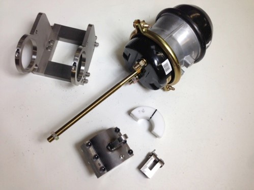
The Dynamic Brake System is a pneumatic/spring
activated brake system that works alongside the mechanical brake linkage. By
welding a stop on the brake equalizer shaft (or using a key stop), an actuator
installed on the equalizer shaft is rotated by the brake chamber when energized
that will then activate the band brake. The actuator is free to rotate on the
equalizer shaft, which allows the mechanical brake linkage to freely rotate the
shaft. Additional benefit is if air pressure supplied to the brake system is low
or lost then the spring in the brake chamber will activate the brake.
Dynamic Brake System Kit includes:
-
- Brake Chamber
- Brake Chamber Harness
- Shaft Spacers
- Actuator Arm and Actuator
- Weld Stop
- Rod Clevis with Pin
- Park Brake Assembly
Dynamic Brake Installation

Installation of Brake Chamber Harness
-
- Chain Brake Handle to Safe Setting
- Clamp Brake Chamber Harness and Spacers to Brake Shaft and brace in final position – Should be full stroke of Brake if no air is supplied to the chamber
- Tack Weld Stop (Half Moon) on Shaft so that the Actuator from Chamber touches the edge
- Weld Stabilizer Clevis to Draw works support beam (see picture below)
- Remove Brake Chamber Assembly and Weld out Stop (Half Moon)
- Install Brake Chamber Harness
- Weld stabilizer (not supplied by PTS) on brake harness plate and connect to Stabilizer Clevis (not supplied by PTS)

Installation of Tubing
-
- Tubing and Fittings not Supplied by PTS
- Find Schematic for Configuration Required
Delivery
Load pin requires 6-8 weeks to fabricate and delivery. Testing
and training can start in advanced before the load limit protection system is installed.
Field-testing is primarily for fine tuning speed control parameters.