Posi-Stop Systems
Posi-Stop Plus System

The Posi-Stop is an independent system that does not
interfere with existing drilling control systems or electronics and can be used on
all Service Rigs (including live shaft draw works), and Production Rigs including
Mechanical, SCR and DC powered rigs. The Posi-Stop block limit control system can be
turned off without interrupting rig operation. If preset upper or lower block limits
have been exceeded, a solenoid-operated pneumatic valve is actuated, the drawworks
clutches and throttle are disengaged, the drawworks brake is applied, and a red
limit light is illuminated. The brake is released and throttle and clutch control is
restored when the red bypass switch is pressed. An amber warning light indicates
when the block is within 5% of the upper or lower limit. An audible alarm also
sounds when the blocks are at the 10% and 95% position and sounds progressively
faster as the blocks approach the lower or upper limit.
For Top Drive rigs the Posi-Stop can add an interface
with the Top Drive console to indicate when the Top Drive unit is in an unsafe
position to travel through the pipe platform zone. The Posi-Stop is configured to
add an “Intermediate” Zone where the block will be stopped if the Top
Drive is in an unsafe position.
The Posi-Stop System can include a block speed control
function to prevent the block from over running the upper and lower limits. Certain
speed and load conditions can cause the block to over run the limits even with the
brake engaged due to inertia. In addition, if the block travel speed exceeds a
pre-set speed at 85% of travel going up, the throttle control can be shut off. This
signal can be supplied to the SCR panel on an electric rig or to the throttle
control on a diesel engine rig. The red limit light flashes if the speed limit is
exceeded in either direction. In addition, the audible alarm sounds three times at
the 30% position in the down direction and at 70% in the up directions.
Block speed is calculated by the Posi-Stop and if
pre-set speed vs position limits are exceeded, a relay is activated at 90% or 95%
when the block is moving up, and at 15%, 10% or 5% when the block is moving down.
This relay will provide a signal to the auxiliary brake to engage when activated.
This is usually connected to a Baylor type brake control but can also interface with
a hydromatic brake or a disk brake. The Posi-Stop monitors the draw works RPM and if
the RPM is above a preset value at the specified block position, the auxiliary brake
is engaged then is released when the RPM decreases below the set minimum. This
provides a reduced block momentum at the upper or lower limit set point.
Data acquisition and transmission capabilities are
available that capture all operating parameters from the Posi-Stop system and
transmit these data via satellite or cellular network for later retrieval and
analysis via the Internet. Position Tracking Systems provides this remote monitoring
and reporting service through “Rigseye”.
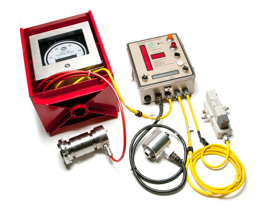
Complete Posi-Stop Plus System Kit includes:
- Posi-Stop Plus Console
- Encoder (Prox Switches or Standard Encoder) to determine speed and block position by counting rotations of the draw works drum
- Encoder Connecting Cable (including connector)
- Electronic Load Pin with wiring harness
- Digital Weight Gauge with connecting cable and protective enclosure
- Solenoid Valve Assembly (Not pictured) to release air supply to clutch and throttle
Complete Standard Posi-Stop System Kit includes:
- Encoder (Proxy Switches or Standard Encoder) to determine speed and block position by counting rotations of the draw works drum
- Encoder Connecting Cable (including connector)
- Solenoid Valve Assembly (Not pictured) to release air supply to clutch and throttle
Rigseye System

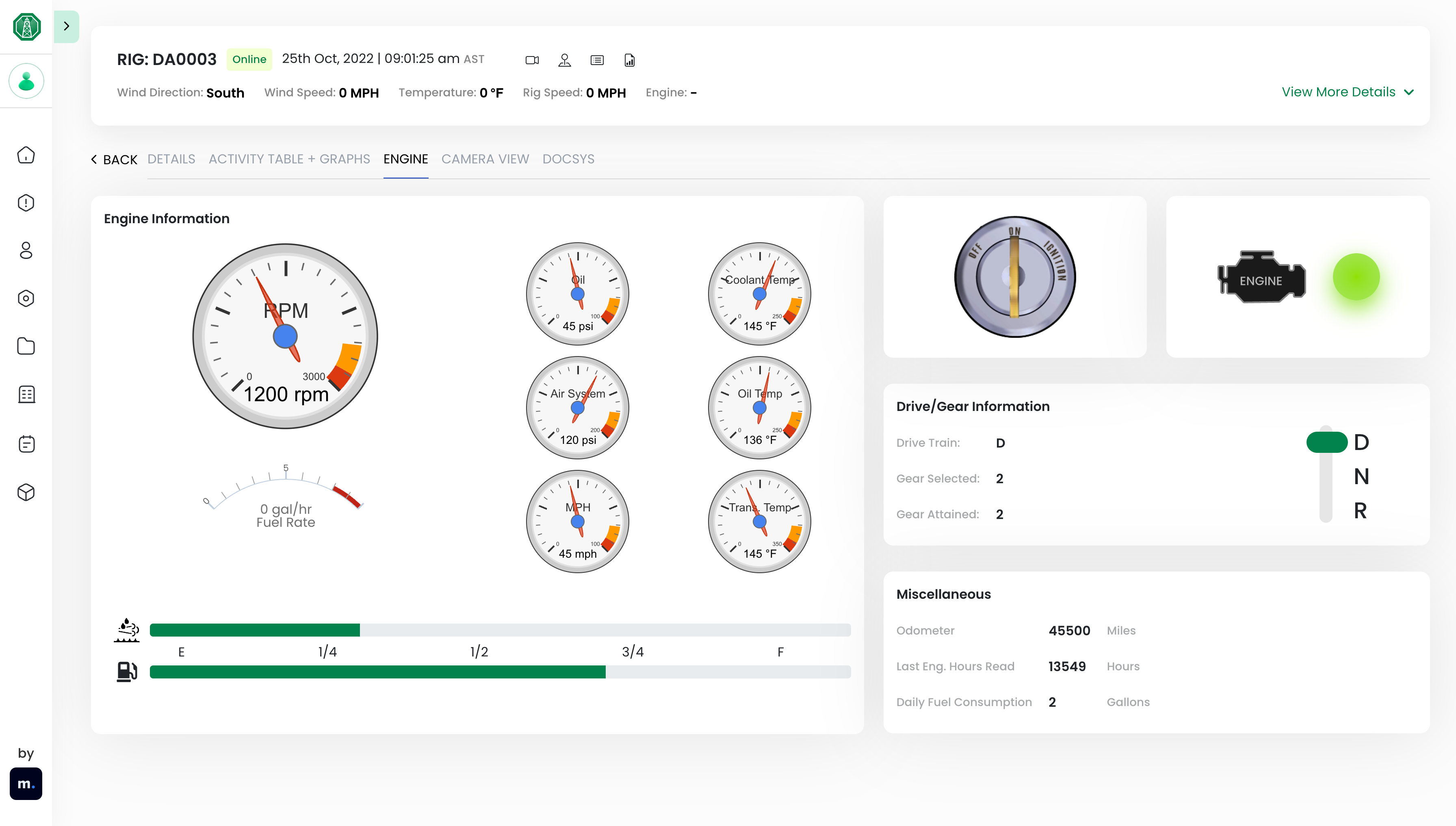
Remote monitoring system that communicates with the
Posi-Stop and the rig’s ECM to collect data that is
sent over the internet to allow remote users real time access to the rigs activity.
Please download this
file for more information.
Spring Set Brake System
The Dynamic Brake System is a pneumatic/spring
activated brake system that works alongside the mechanical brake linkage. By welding
a stop on the brake equalizer shaft (or using a key stop), an actuator installed on
the equalizer shaft is rotated by the brake chamber when energized that will then
activate the band brake. The actuator is free to rotate on the equalizer shaft,
which allows the mechanical brake linkage to freely rotate the shaft. Additional
benefit is if air pressure supplied to the brake system is low or lost then the
spring in the brake chamber will activate the brake.
A Brake Handle can be added to this brake to allow the
operator to operate the brake chamber with a handle mounted at the end of the brake
lever. This allows the operator to maintain contact with the brake lever and use
wrist to operate the brakes to lower fatigue.
“Deadman” Brake is a lever mounted on the
handle that must be held down to allow normal operation of the drawworks. If contact
is not made on the lever then the brake is set and air flow to the throttle is
stopped.
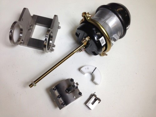
Dynamic Brake System Kit includes:
- Brake Chamber
- Brake Chamber Harness
- Shaft Spacers
- Actuator Arm and Actuator
- Weld Stop
- Rod Clevis with Pin
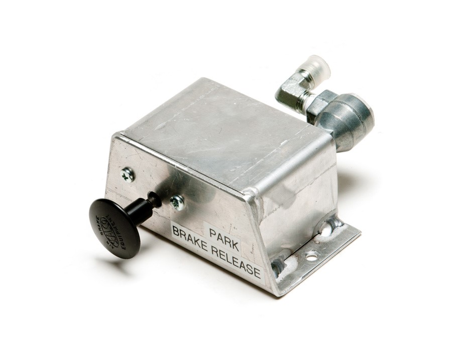
- Park Brake Assembly
- Brake Handle Assembly (Optional)
- “Deadman” Brake Assembly (Optional)
Standard Brake System
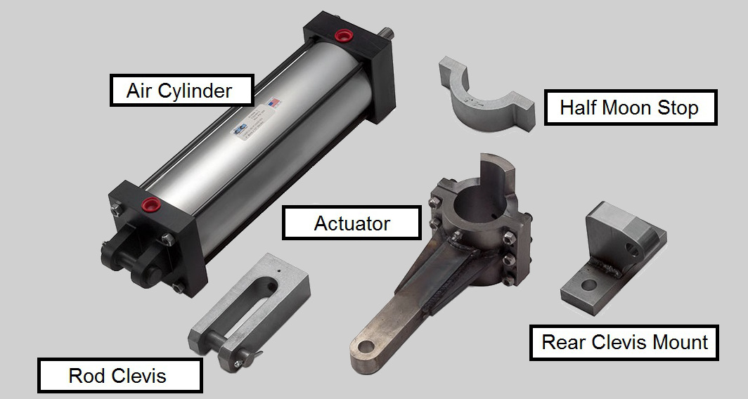
The Standard Brake System works by applying air to a
cylinder that either pushes or pulls a shaft that is connected to an actuator on the
equalizer shaft of the band brakes. This will rotate the equalizer shaft and thus
closing the band with the brake pads around the drum. The “Posi-Stop”
system applies the brakes when limit conditions are met by activating a solenoid
valve that opens the air circuit to the air cylinder.
Standard Brake System Kit includes the following:
- Air Cylinder
- Rear Clevis Mount
- Rod Clevis
- Actuator
- Half Moon Actuator Stop
Load Limit Load Pin
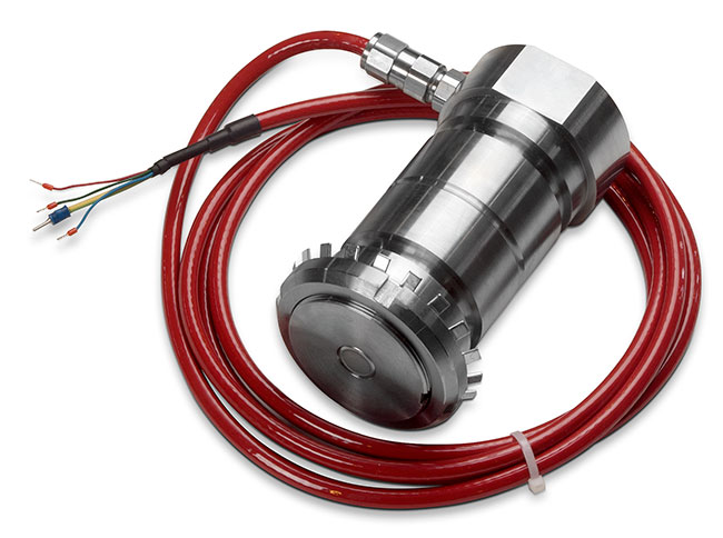
- Mounted in dead line sheave
- Load Pins that are easily incorporated into the load path
- Easily calibrated to match analog weight indicator gauge reading
Digital Weight Gauge System Component
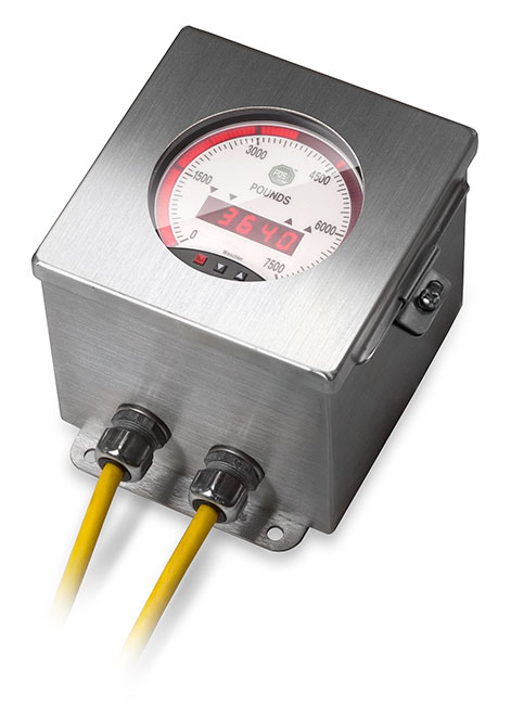
- Weight gauge instrument easily calibrated to load pin or load cell
- Super bright display
Foot Bypass
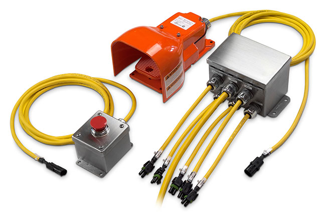
- Integration into the Posi-Stop System
- Allows operator to bypass brake system through a covered foot pedal
- Eliminate delay in brake activation and release time
- Allows operator to move the blocks through the lower and upper limit set points without activating the brake
- Timeout feature allow the foot switch limit bypass to engage for five seconds – after which, the limit control is reactivated
Delivery
Load pin requires 6-8 weeks to fabricate and delivery.
Digital Gauge 6 weeks and all other items 2 weeks.
Request a Quote
Note: Load Pin and Weight Gauge require Plus Console to operate.